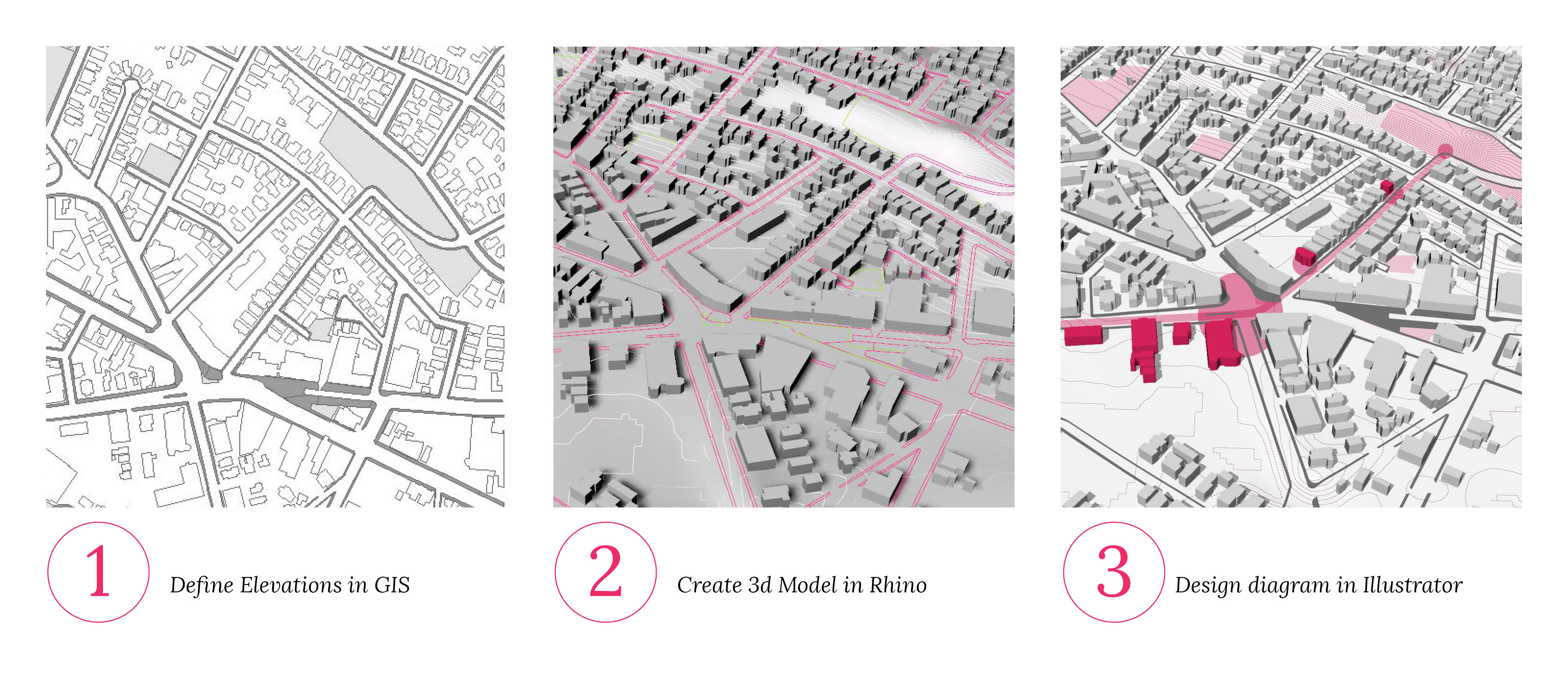
GIS to Rhino


Tutorial Information
- Module 5 in Design and Representation for Planners.
Methods
Tools
ArcMap Setup
Open ArcMap and upload the following layers: 1. contours_clip 2. Somerville_bldg 3. Somerville_sidewalk 4. Somerville_openSpace 5. Study_area_05
** The contour layer was derived from a Digital Elevation Model (DEM), which produces clean and continues contour lines. This method is preferred to the overly detailed contour lines available through municipalities’ websites, that are usually not continues or closed polygons.
Generate topography polygons
1. Create line feature from the study area box.
Data Management Tools -> Features -> Feature to Line
Input Features: Study_area_05 Output Feature Class: ~/Box_Line
2. Merge box line with contours
Select Contours. Data Management Tools -> General -> Append
Input Datasets: Box_Line Target Dataset: contours_clip Schema Type: NO_TEST (IMPORTANT!!!!)
3 .Convert merged box/contours into a polygon layer.
Data Management Tools -> Features -> Feature to Polygon
Input Features: Contours Output Feature Class: ~/ContoursPolygon
4 . Spatially join polygons with contours to obtain elevations
- Right-click ContoursPolygon layer in Table of Contents.
- Joins and Relates -> Join
What do you want to join to this layer? Join data from another layer based on spatial location.
- Select Contours as the layer to be joined.
- Select “Each polygon will be given a summary…”
- Check the “Maximum” box.
Output: ~/ContoursPolygon_Elev
Congrats! you’ve successfully created topography polygons.
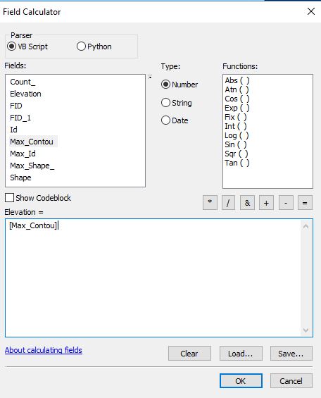
5. Add elevation field to ContoursPolygon_Elev attribute table
This step creates a new field called Elevation in the attribute table and populates it with the values recieved from the max function earlier. This step is needed for 2 reasons: 1. Clarity. 2. Rhino needs this field to read the polygons’ elevation.
- Right-click ContoursPolygon_Elev layer in table of Content
- Open attribute table -> Add Field -> Field name: Elevation
- Right-click on Elevation field -> Field Calculator
- Elevation = [Max_Contou]
Based on topography, Add elevations to building footprints
1. Join the building footprints with the elevation data
- Right-click Building Footprints layer in Table of Contents.
- Joins and Relates -> Join
What do you want to join to this layer? Join data from another layer based on spatial location.
- Select ContoursPolygon_Elev as the layer to be joined.
- Select “Each polygon will be given a summary…”
- Check the “Minimum” box.
Output: ~/BuildingFootprints_Contours
2. Add elevation to building height.
Open the attribute table for BuildingFootprints_Contours
- Create new field called “Elevation”
- Right click the field name and open the field calculator.
- Elevation = 30 + [Min_Elevat]
3.
Check to make sure all fields you will be exporting to DWG files include
an elevation field.
Export to DWG for AutoCAD or
Rhino
1. Select layers to export
In Table of Contents Layers window, right click the
ContoursPolygon_Elev layer: Data -> Export to CAD
2. Export settings
Input feature: select BuildingFootprints_Contours to add it for CAD
export. Create a new folder to save this file as an output from GIS.
- IMPORTANT NOTE: All layers should have identical Projected
Coordinate System (in this tutorial:
NAD_1983_StatePlane_Massachusetts_Mainland_FIPS_2001_Feet) when
exporting a single DWG file with multiple layers. If there are mixed
coordinate systems, you may find layers do not place in the same place
when importing the DWG into Rhino.
Import DWG in Rhino
1. Launch Rhino
Open Rhino and create a new file (Large Object: Feet). The linear
unit should be the same with your GIS file’s projected coordinate
system. We will introduce more about the interface, views, commend, and
layer management in Rhino.
2. Loading DWG into Rhino
Insert the DWG file into Rhino. We will discuss the difference
between Insert and Import.
3. View and layer management
View management: Type “Zoom” in commend window -> Extend, to
zoom to the DWG file.Layer management: In Layer Panel, you will see the identical
layers in Rhino as ArcGIS. You can manage the layers by 1) assign the
current layer; 2) turn on/off the layer; 3) rename; and 4) restyle the
layer with different colors and line weight.
Congratulations! Now you’ve successfully exported GIS data as a DWG
file (drawing file) and imported in Rhino for 3D creation. Move forward
to the next session on generating topography, extrusion, and render in
Rhino.