From 3-D to Vector


Tutorial Information
- Module 6 in Design and Representation for Planners.
Methods
Tools
Last week, we followed a procedure to export GIS Layers to Rhino. This means that we now have a 3-dimensional model that leverages properties of our spatial data—namely, its included ‘elevation’ field—which we can build upon using any of Rhino’s modeling tools. This is where we can start drawing upon (a model of) the ground! But first, we’ll flesh out our model, making it properly volumetric.
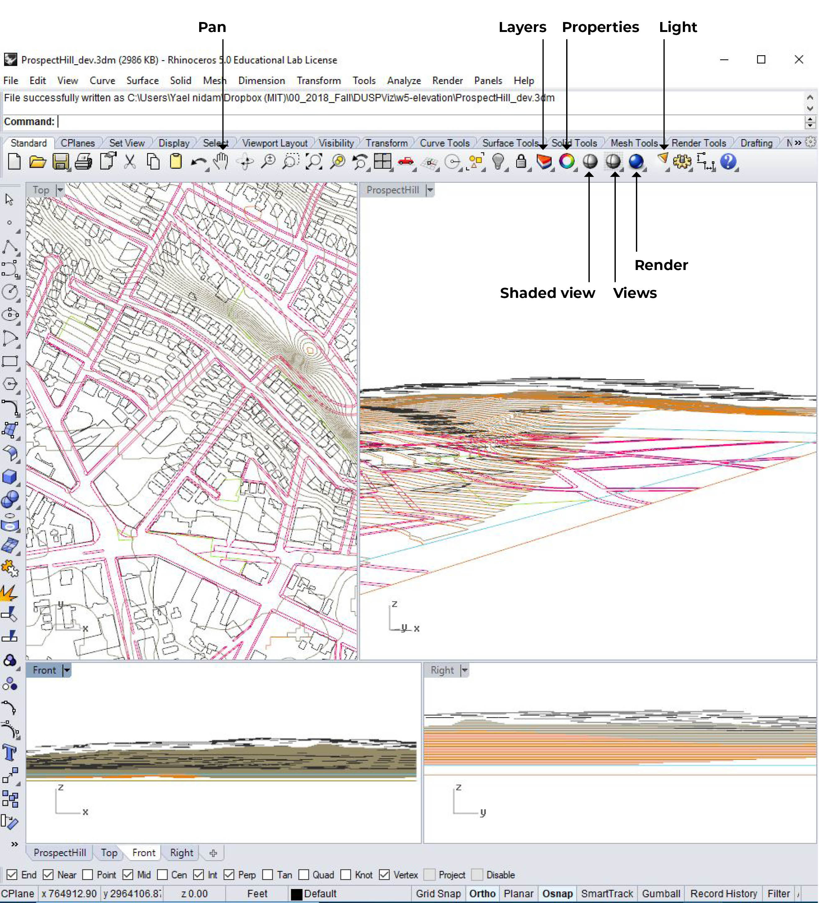
Now, open Rhino and check out the layers:
BuildingFootprints_Contours2ContoursPolygon_Elev2Somerville_openSpaceSomerville_sidewalkStudy_area_05contours_clip
You will see that (1) BuildingFootprints_Contours2 places each building polygon at the exact top height it should reach. (2) ContoursPolygon_Elev2 is a layer that contains a separate polygon for each topography level. This will be a good layer if we wanted to laser cut the topography, but it’s not the best choice for a 3d topography because it will create a terraced model. We exported this layer so you can see the difference between this layer and contours_clip, which includes one topography line for each level. And lastly, both Somerville_sidewalk and Somerville_openSpace are placed at zero elevation and will need to be projected onto the topography.
Generate Topography
Create a New layer Named Topography
- Go to the layers’ menu and click on the new layer icon.
- Double click on the layer to rename it to Topography.
- Under the V column, double click the Topography row so that the V for current layer will be on Topography.
Turn Off All Layers But contours_clip
In the layers’ menu and turn off the light icon for all layers but contours_clip
Select All Topography Polygons
- Choose one of the 4 views (either top, perspective, front or right).
- Zoom out (scroll out) until you see all polygons.
- Left click to select all polygons, release click only when you have finished selection. Notice that if you move your mouse to the left, the selection rectangle is a continues line and will only select objects inside the line. If you more your mouse left during selection, the selection line will be broken and the selection will include any object that crosses the line as well as all the objects inscribed.
- You will see all selected objects will change color to yellow
Use Patch to Create 3d Topography
In the command line print: patch
Define:
- Sample point spacing: 0.5
- Surface U spans: 50
- Surface V spans: 50
- Stiffness: 2
Check boxes for Adjust tangency and automatic trim. After a brief pause, you should have a topographic model of your site.
Trip topography
Let’s trim the edges of the topographic model; the patch command creates an interpolated surface that extends beyond the edges of the features that generate it. We want to only represent terrain within our study area.
Use the trim command, selecting the study area bounding
box (study_area_05) as our cutting object and the
topography as our object to trim. Make sure ‘extend lines’ and ‘apparent
intersections’ are both selected.
Project Sidewalks and Open Space to Topography
Adjust Layers
- Create a new layer named projected_sidewalk and make it the current layer.
- Turn on somerville_sidewalk.
- Lock all layers but projected_sidewalk and somerville_sidewalk.
Project Sidewalks to Topography
- In the command line print: project
- The command line will prompt you to select curves and points to project. Select all sidewalk polylines and press enter.
- The command line will now prompt you to select the surfaces you wish to project onto. Go to the layers menu and unlock Topography layer. Select the topography we just created and press enter.
Repeat
the above steps to Project Open Spaces Onto Topography.
Extrude Buildings
This step will demonstrate why part 1/3 GIS to Rhino tutorial was so
helpful.
Adjust Layers
- Create a new layer named buildings_extrude and make it the current
layer. - Turn on BuildingFootprints_Contours2.
- Lock all layers but BuildingFootprints_Contours2 and
buildings_extrude.
Use Extrude to Create
Building Volume
- In the command line, print: extrudecrv and press enter
- Choose all buildings and press enter
- In the command line, click on ToBoundry and choose the topography
layer (you have to unlock it first). - in the command line print: 30 and enter.
If your buildings fail to
extrude…
- In the command line, print: extrudecrv and press enter
- Choose all buildings and press enter
- in the command line print: -30
- In this case we choose -30 because we know our tallest building is
30 feet. In other models always choose the tallest elevation so that the
tallest building will touch the ground.
Optional:
Use Boolean Difference to Remove Building Area Underneath
Topography
- Duplicate Topography layer. Create a new layer called: topo-copy.
Use the copy command to duplicate 3d topography. use the properties menu
to place the duplicated version in the topo-copy layer. - In the command line type: BooleanDifference
- Select surfaces/polysurfaces to subtract from - choose all
3Dbuildings and press enter. - Select surfaces to substract with - Choose topo-copy.
- Wait 1-2 minutes for the computer to finish processing.
View, Light, Materials &
render
Set View
- Change the perspective viewport’s properties such that it uses
parallel projection instead of perspective
(view > viewpoint properties). This is because we want
an isometric drawing; one in which dimensions appear the same regardless
of their distance from the camera. - Create a new layer called
camera_guide. - In the top viewport, create a new line of arbitrary length at a 0
degree angle (this will be used to set the camera and its target). To do
this, add a polyline (Polylinecommand) and hold
shift. - In the front viewport, rotate it up from the ground plane by 30
degrees (typerotate, select the endpoints of the line, and
enter30). In the top viewport, rotate it so that it makes
an angle appropriate for the area under consideration. - Make sure the perspective viewport is active. Navigate to “Place
Camera and Target” (View > Set Camera). Place the camera at the
elevated end of the line, and place the target at the end of the line in
contact with the ground plane. Now adjust the zoom settings until the
frame is positioned as desired.
Save View
- Make sure Rhino window is maximized.
- Click on the small arrow next to the perspective tab. Choose set
view -> Named view. - In the pop-up window click on the save icon and name your view
(isometricmight be a good name). - Double click on your named view so you can see all 4 views together
again.
Create Light
- Use the light icon to create directional light.
- Use the top view to locate the light at the south end of your model
and choose an angle that is slightly rotated to the east. - In one of the sectional views rotate the light to a desired angle.
(Command line: rotate).
Materials
For the purpose of this exercise we want a white render that will be
used to add shadow to our final graphic. Remember, the render functions
only renders 3D objects, so there is no need to define materials for
layers that contain line work. Go to the layers menu and define
materials for Topography and 3Dbuildings:
- Topography: white (RGB 255,255,255)
- 3Dbuildings: white (RGB 255,255,255).
Render Settings
Press on the small arrow next to the render bottom and choose: render
settings. In the pop up document properties window define:
- Resolution: 1920X1080 (standard HD monitor resolution)
- DPI: 150 (magazine quality, choose 300DPI if you print with
inkjet) - Ambient light: black (in this case because we’re interested in
shadow only) - Background: transparent.
- After defining render settings, set the view to your named isometric
view and render. In the render window choose Gamma Correction: 2.2 and
export JPEG.
Export to Illustrator.
Export all lines
- Go to the layers menu and make sure all layers are turned on and are
unlocked. - ctrl A / Command A to select all objects.
- File -> Export Selected -> choose .ai file type.
Use make2D to export
buildings’ contours
- In the layers menu turn off all layers but 3Dbuildings.
- Set the view to your named perspective view.
- ctrl A / Command A to select all objects.
- In the command line: make2D
- drawing layout: Current view
- Options: Check only the box for: Maintain Source Layers.
This function will create a 2D linework of your perspective. to view
it:
- Go to top view
- Turn all layers off but the Make2D layers.
- In the command line: Zoom -> Extents
- Select all + export to Illustrator.